


Description
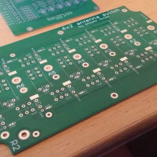
The 6×2 is an antenna switch which can route 6 antennas to 2 radios. The kit consist of two PCBs, one which is for the RF part that route the actual antennas to the radios and one board which contains a bunch of relays which used to interlock the radios in a fashion that first wins. So if for example radio 1 has selected antenna 5 and radio 2 tries to select it nothing will happen. The RF board is also designed in such a way with three relays per antenna port making it impossible if the interlock for some reason fails to actually connect radio 1 and radio 2 together. The extra relay also increases the isolation between the ports. This version of the 6×2 is built for 7/16 connectors and has got more isolation than the other 6×2 version.
Typical isolation between the ports is 80dB on 28 MHz, 90dB on 14 MHz and 95dB on 1.8 MHz. It varies a bit depending on which port is measured between which can be seen on the measurements below. The insertion loss is typically around 0.08dB on 28 MHz and 0.05dB on 14 MHz.
To get the lowest insertion loss the Radio A/B connectors should be mounted on the side of the board and an series inductor should be inserted between the connect and the board. This will get the insertion loss down to the values in the measurements mentioned. If you don’t have access to any kind of VNA to measure the insertion loss, you can connect the connectors directly into the board. You will get about 0.1-0.15dB more insertion loss but it does not make much influcance on the isolation between ports.
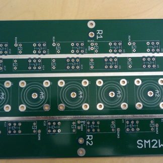
On the boards there is an opening in the solder mask where its best if you solder a shield between the relays. This will increase the isolation between the radios and I have noticed lately that it is also good if you connect the two shields together on the top as well. You don’t need to solder it all the way, since if something fails it will be very hard to get it removed.
The RF board has got 140um thick copper, and I know antenna switches being used with > OM-3500 type of power levels without any problems.
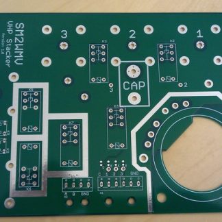
RF board top view – If used as a drilling template, make sure to print is with 1:1 scale
Reviews
There are no reviews yet.