Category Archives: Electronics - Page 21

Filter design

I was trying this weekend to build a Cauer LP filter that I designed for 80m with notch at 7.1 MHz. I did not get the performance of the filter as I wanted and they are quite hard to tune with those big pipes etc to bend. So instead I decided to go for a design very similar to the one ON4UN describe in his book with notches instead. Those are easy to adjust since you see very well what you are doing and also they do not have a big impact on the other notches. Another advantage is that you can get very low insertion loss and for this filter I was aiming for better than 0.1dB. I decided to skip the notch for 160m but I might add a notch small enough so that It does not impact the insertion loss and give maybe 20dB of depth. I also need to add the rest of the box and fine tune the notches so that they are behaving as they should.

The idea is that I will build these filters for the radio 1 and radio 2 position in the switching system. On 160/80m where we just have one antenna it will sit directly at the antenna and be used on all four radios. The notches both remove the harmonics generated by the amplifier but will also remove other transmitting radios main tone. I will build another filter for 40 and probably also rebuild the 20m LP-filter I built earlier as well to a notch filter.

I got VERY happy with the result, maybe I would have wished the 40m notch would be slightly deeper and could probably be possible by fine tuning the series inductor but I would need to make another one, so I think I will just stick with the current design.

Attenuation on 3.755 MHz is 0.05dB which is a lot better than the 0.1dB that I had as goal.
40m -> -56dB
20m -> -53dB
15m -> -66dB
10m -> -72dB

The yard got cleaned up

This weekend SM2LIY was working the Scandinavian Activity Contest as SOAB LP. We did not know that the ACOM 2000A that we got sponsored by Ojojoj Music AB would show up before the contest, so SM2LIY was signed up for SOAB LP on the Swedish “National Team” in the contest. The propagation’s during the night with aurora ruined the chances of taking a new Swedish record, but Pelle seem to finish in second place after OH5Z.

On Friday I did connect the last antennas since we dug the cables down in the ground earlier in the summer, to prepare for the contest. I also built a mould which will be used to make the concrete base for the 40m tower. Hopefully next weekend we get to borrow an L70 tractor to get some gravel and maybe the concrete mixer from my neighbor, so we can start making the base for the tower.

On Saturday SM2XJP had borrowed a tractor that we used to move the tower sections and all the wood left from the house work during the summer. I have a small hay barn which is 20m2 that has been standing empty, so we moved the wood there and also the insulating material which was left for the last wall of the house, which will be finished next year. When SM2XJP got tired in his clutch foot I got to drive the tractor which was a lot of fun but when it got too exciting he got to take over 🙂 Now the yard is starting to look decent again but still some cleaning to do before we can call it ready for the winter, which hopefully wont arrive in a while if we are going to get that 40m tower up.

SG3P has borrowed me an TS480HX that I will be using to remote control the station. The openASC system is supporting control of all antennas etc remotely and now I’ve started to make it so that we can control it over ethernet as well, which will make it even more neat. However to make the station fully steerable I will need to add my rotator boards into the rotator controllers so we can turn the antennas remotely.

We got sponsored by SM2O and his Microbit 2.0 AB company with lots of remote gear. The well known remoterig system which is an excellent product to make remote operation enjoyable with very low latency, possibility to send clean CW etc. All in all we got a complete set of RRC-1258MkII with an extra control unit for SM2XJP, a Webswitch 1216H and also an RC-1216H for controlling the ACOM amplifier. I soldered some cables for this so hopefully I will have it operational after the weekend!

Stay tuned…

A little update

Last weekend some more things got done at SJ2W. On Friday me and SM2XJP paid SM2DMU a visit. We picked up a bearing which is used as a guy wire ring. He used it on one of his towers but unfortunately it fell down a few years ago and one of the rings was left over since the parts of the tower that weren’t damaged, was enough to be guyed at one level. Thus we could take it and I will drill a few new holes in it to match our current tower. So we thank Rainer a lot for giving us that guy wire ring along with 10 pcs of M12 A4 stainless steel threaded rods.

I also noticed that when I drilled 15mm holes in the H-beams it was too small. I thought it was M14 but unfortunately it was M16, so now I have taken them up to work again where I will drill the holes bigger so it fits properly.

I also got some work on the house done and hopefully in a couple of weekends it will be done for this year and it will be all radio work from now on.

I left my phone at SJ2W, so I might be hard to get in touch with until Friday when I will be back. That also means no pictures, since I use the phone to take them.

Today I built a preamp with a GALI-74+ amplifier from mini-circuits. It seem to work well, about 24dB amplification and according to the specifications it should have 2.7dB Noise-Figure and IP3 of +38dBm. That is specified at 1 GHz though, I am not sure what we can see at 1-30 MHz, but hopefully it works well. I have also gotten all the 500m of RG-6 that I ordered so now we will put up a vertical about 600m from the TX antennas and see how much QRM we get when listening on the same band as the run station.

To be continued…

SJ2W QRP

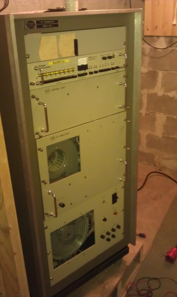
Yes, today our only fully working amplifier broke, its a Granger Model 180-1 HF transmitter which we use the amplifier part of and has got a 4CX1500B tube. If you have any details on this amplifier, like a manual I would really appricitate it. I have been looking but can neither find what happened to the Granger company or any manual of the amplifier.

It seems like the bias voltage on the control grid which is the problem causing the tube to draw maximum anode current, and that makes the protective circuits to trip. However, its hard to find what is actually for the bias in the ratsnest of wires. So a manual would be really helpful, since santa seem to reject my wishes of a new amplifier.

This got me in a very bad mood…

Here is a quite bad picture of the amplifier,