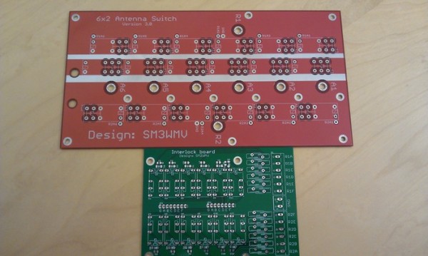
The 6×2 is an antenna switch which can route 6 antennas to 2 radios. The kit consist of two PCBs, one which is for the RF part that route the actual antennas to the radios and one board which contains a bunch of relays which used to interlock the radios in a fashion that first wins. So if for example radio 1 has selected antenna 5 and radio 2 tries to select it nothing will happen. The RF board is also designed in such a way with three relays per antenna port making it impossible if the interlock for some reason fails to actually connect radio 1 and radio 2 together. The extra relay also increases the isolation between the ports.
Typical isolation between the ports is 70dB on 28 MHz, 80dB on 14 MHz and 90dB on 1.8 MHz. It varies a bit depending on which port is measured between which can be seen on the measurements below. The insertion loss is typically around 0.06dB on 28 MHz and 0.03dB on 14 MHz.
To get the lowest insertion loss the Radio A/B connectors should be mounted on the side of the board and an series inductor should be inserted between the connect and the board. This will get the insertion loss down to the values in the measurements mentioned. If you don’t have access to any kind of VNA to measure the insertion loss, you can connect the connectors directly into the board. You will get about 0.1-0.15dB more insertion loss but it does not make much influcance on the isolation between ports.
On the boards there is an opening in the solder mask where its best if you solder a shield between the relays. This will increase the isolation between the radios and I have noticed lately that it is also good if you connect the two shields together on the top as well. You don’t need to solder it all the way, since if something fails it will be very hard to get it removed. I would also recommend that you solder 100nF or similar ceramic capacitors over the relay coils on the RF board. The easiest way is just to solder this on the bottom side of the card directly at the pins for the relays.
The RF board has got 140um thick copper, and I know antenna switches being used with > OM-3500 type of power levels without any problems.
List compiled by G4AON if ordering from rapid (note it’s for the 6×1 but most parts match)
Reichelt shopping cart made by DM2RM – modified by DM4IM and me
RF board top view – If used as a drilling template, make sure to print is with 1:1 scale


Hi have been using Mike’s boards (6X1, 6X2, STACK) for many years and no single issue of them! Even built some for some friends and everyone is happy with them!
Way to go Mikey!
Filipe CT1ILT aka CR6K
Hi, how much power will the switch handle using the relays in G4AON”s kit list?
73
Denis MW0CBC / GW8OQV
Does not really matter that much which type of relay you use, they are all built quite equally and handle about the same amount of power. So it handles OM-3500 type of power levels.
Thanks for that. I shall be placing an order 🙂
Best wishes
Denis
I built 2 of the 6×2 antenna switches and added a little PIC controller for automatic switching. Works like a charme and was an easy project for my daughter and me.
cu in the contests
Holger ZL2IO/ZL3IO/ZM4T
Be warned! The last batch of Coax-sockets we bought from Reichelt are real Junk! They don’t solder well and if you apply heat for to long, the pin falls out, because the material around the pin is not PTFE. Further, a SO-239 plug slides in way to easy, so i suspect there will be no good contact.
You better buy quality e.g. kabel-kusch.de
73!
If turn de TRX on one of the antennas,and can turn the secund trx same antenna simultaneously ?
73 Laci
Hello no, you can not turn the second TRX to the same antenna. There is an interlock function which makes that impossible plus there is also a switching relay that toggles between R1 or R2 on the 6×2 RF boards which also avoids it so there is double safety for this.
Why does the addition of the series inductor reduce the insertion loss?