Description
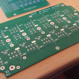
Note that this is only the Printed Circuit Boards, no components are sold with this.
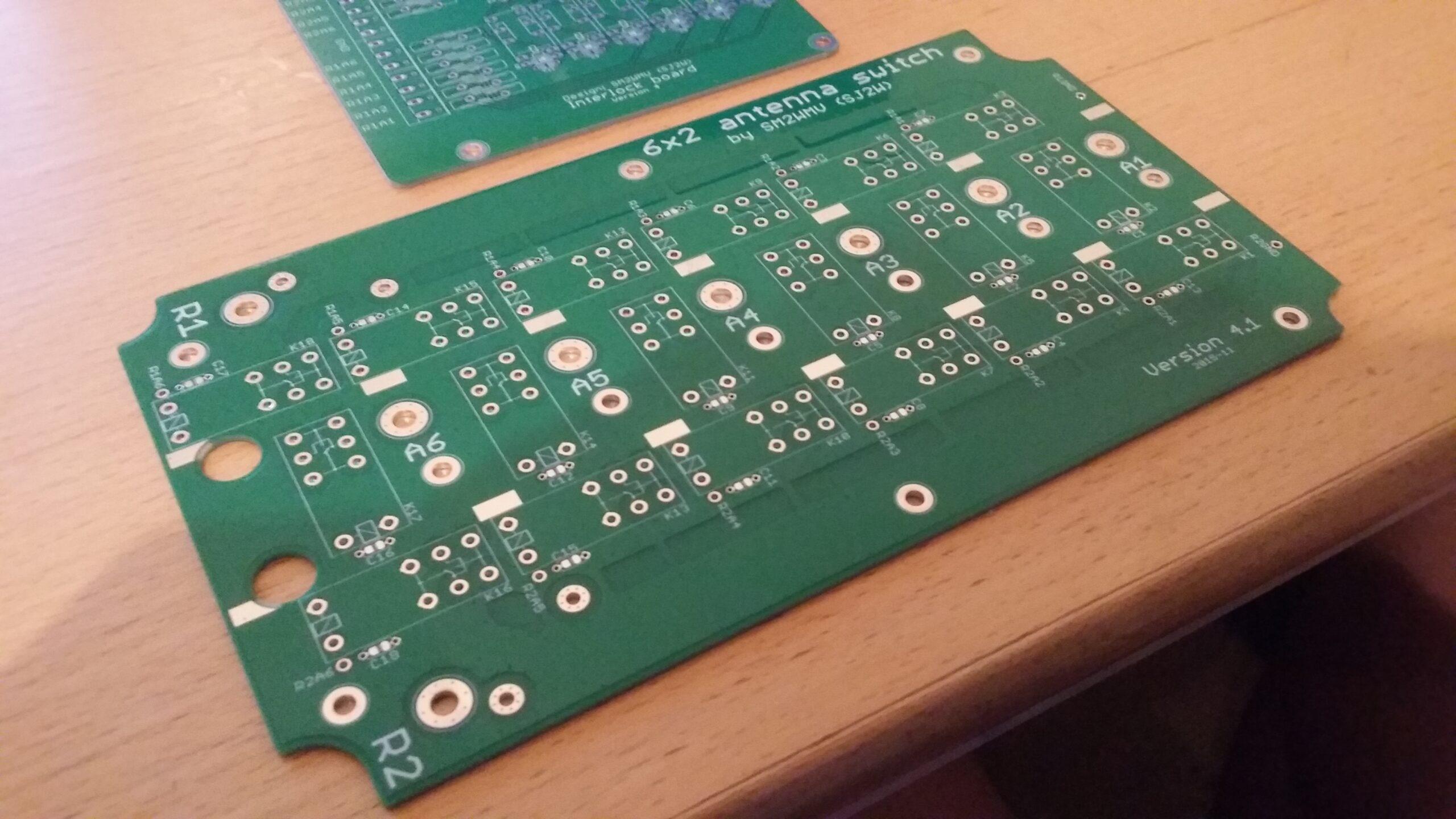
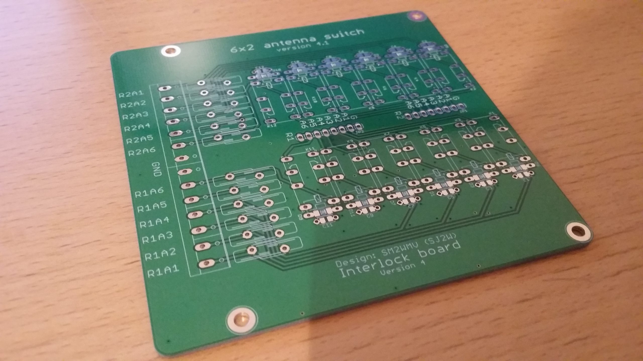
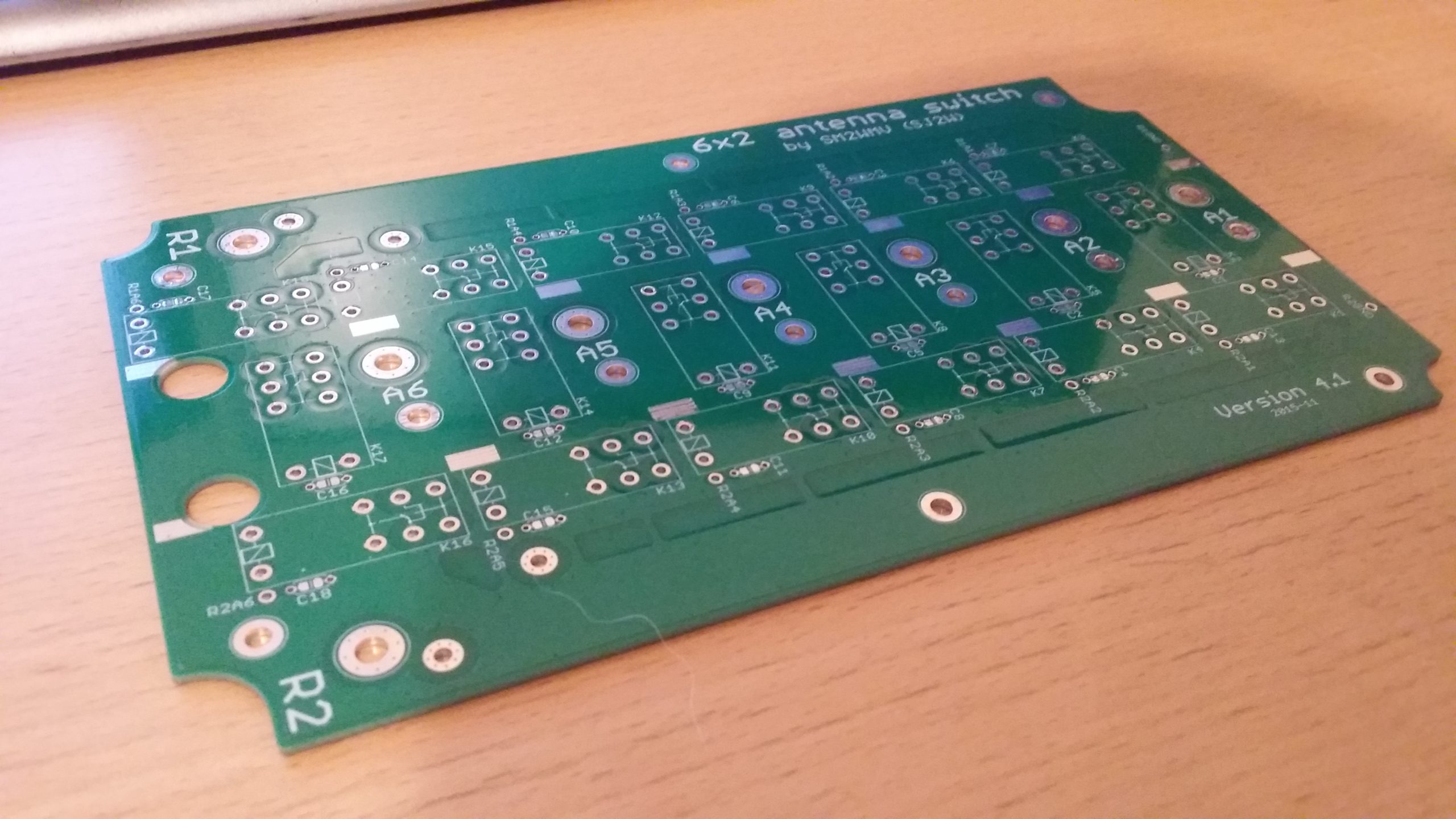
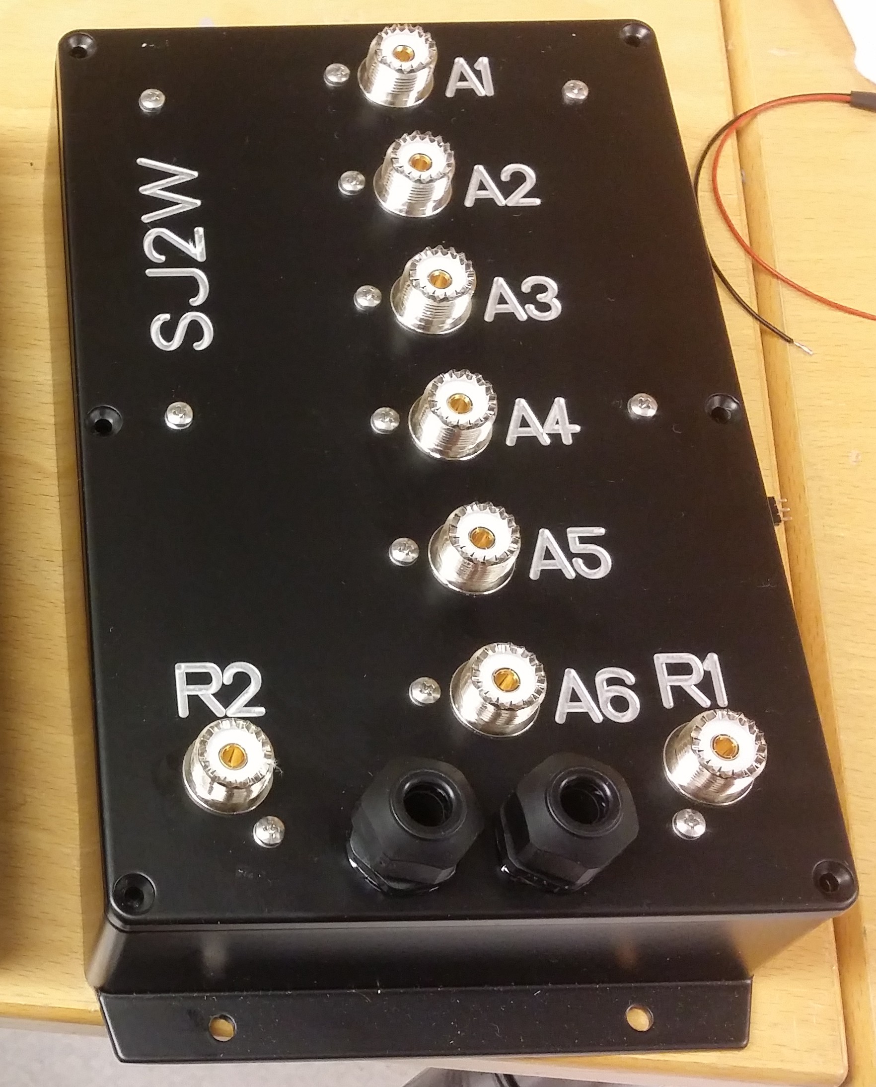
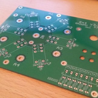
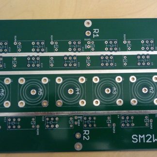
The 6×2 is an antenna switch which can route 6 antennas to 2 radios. The switch consist of two PCBs, one which is for the RF part that route the actual antennas to the radios and one board which contains a bunch of relays which used to interlock the radios in a fashion that first wins. So if for example radio 1 has selected antenna 5 and radio 2 tries to select it nothing will happen. The RF board is also designed in such a way with three relays per antenna port making it impossible if the interlock for some reason fails to actually connect radio 1 and radio 2 together. The extra relay also increases the isolation between the ports. Any unused antenna port is connected to ground to avoid problems with static such as lightning etc.
The device uses positive switching, which means all the relays use common ground. So to enable an antenna you would add a voltage of +12V on the control line. 2×7 leads are needed to control the box, so a couple of network cables are perfect to switch it.
The difference between this 6×2 and the previous version 3 is that it has got slightly better performance, it is designed for a box in mind and works also on 6m since it has got lower insertion loss than the old version. It has also gotten decoupling capacitors added also on the RF board plus the series compensation inductance has now got an own position on the board. The interlock board also has got proper mounting positions to be mounted directly on top of current holes in the RF-board.
Isolation (Depending on port, between R1 and R2)
50 MHz: -57 to -70dB
28 MHz: -61dB to -80dB
14 MHz: -68dB to -85dB
3.5 MHz: -85dB to -100dB
Typical insertion loss 1.8 – 28 MHz < -0.06 dB
Typical insertion loss 50 MHz < -0.10 dB
Typical VSWR 1.8 – 28 MHz < 1.15:1
Typical VSWR 50 MHz < 1.3:1
Power rating (1.8-30 MHz, SWR <1.3:1) 5kW
Power rating (1.8-30 MHz, SWR <2:1) 2.5kW
Power rating (1.8-30 MHz, SWR <3:1) 1.5kW
Power rating 50 MHz 2.5kW
Top print of board (scale 1:1)
Remember to always disable scaling when printing the top print of the board to use as a drill template, so that you are sure you are having a 1:1 scale print.
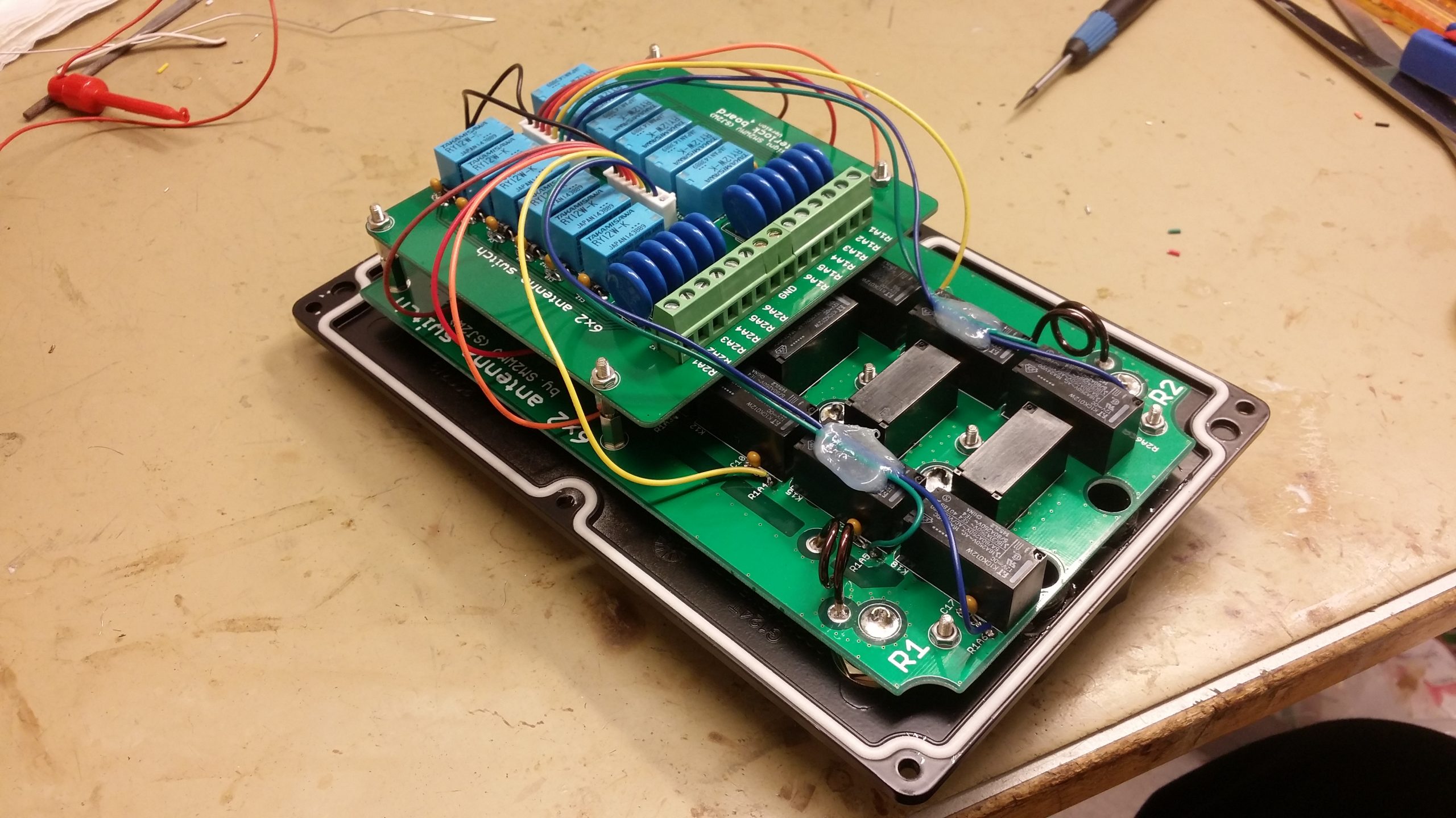
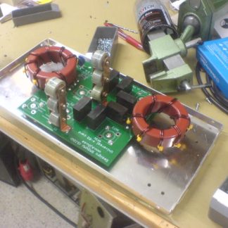
To get optimal performance out of the switch with lower insertion loss, an inductor should be soldered on the board as can be seen on the pictures. A good starting is to wind 1.5 turn around a 10mm rod (for example a drill bit) and have them closely spaced. This is adequate to get close to best performance but to be really sure you can measure it with some type of VNA.
It is also recommended that you think through were to put the antennas on which port. As can be seen in the measurements you will typically depending on the compensation coil have lower insertion loss on port 1 and less good high frequency performance on port 6. This is because of the coil being an average solution over the frequency range. Also there is always less isolation between two adjacent antenna ports. So if you have antennas closed spaced on certain bands it might be a good idea to separate them with at least one antenna port between. Remember that even such a low increase in isolation as 3dB will be the same as you dropping your power in half.
Reviews
There are no reviews yet.