Description
Note that this is only the Printed Circuit Board, no components are sold with this.
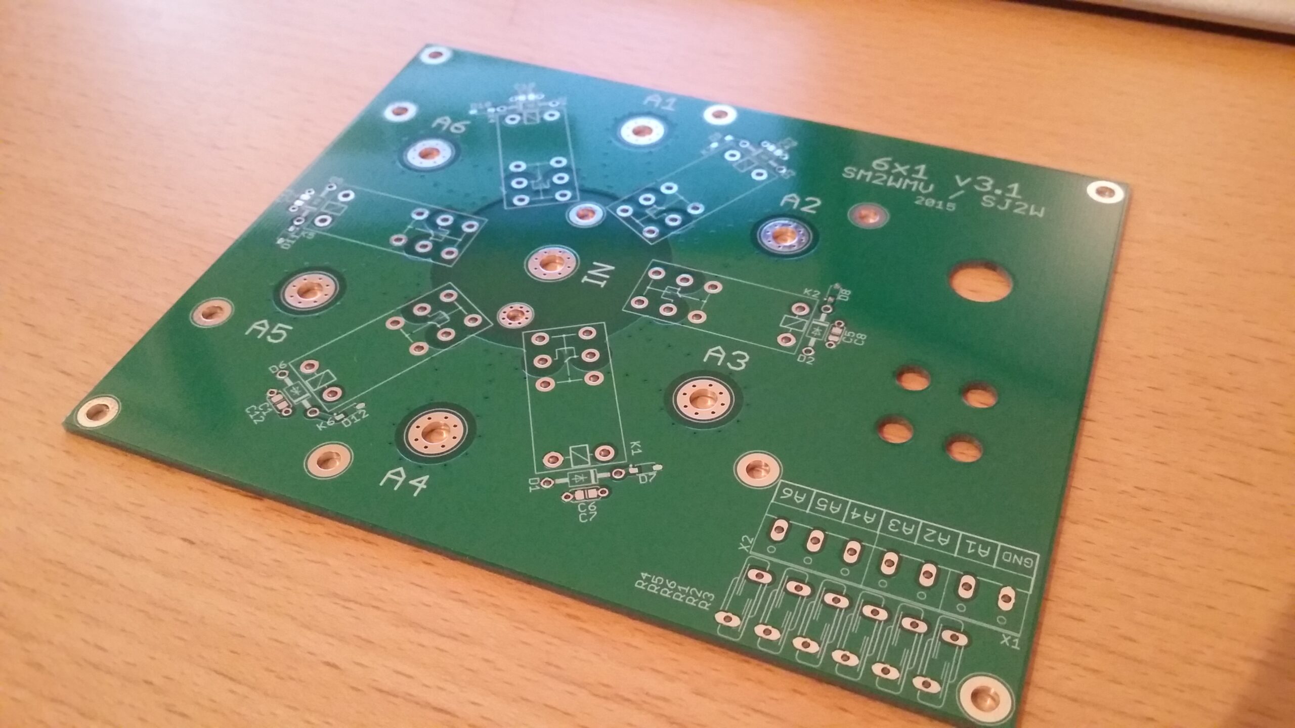
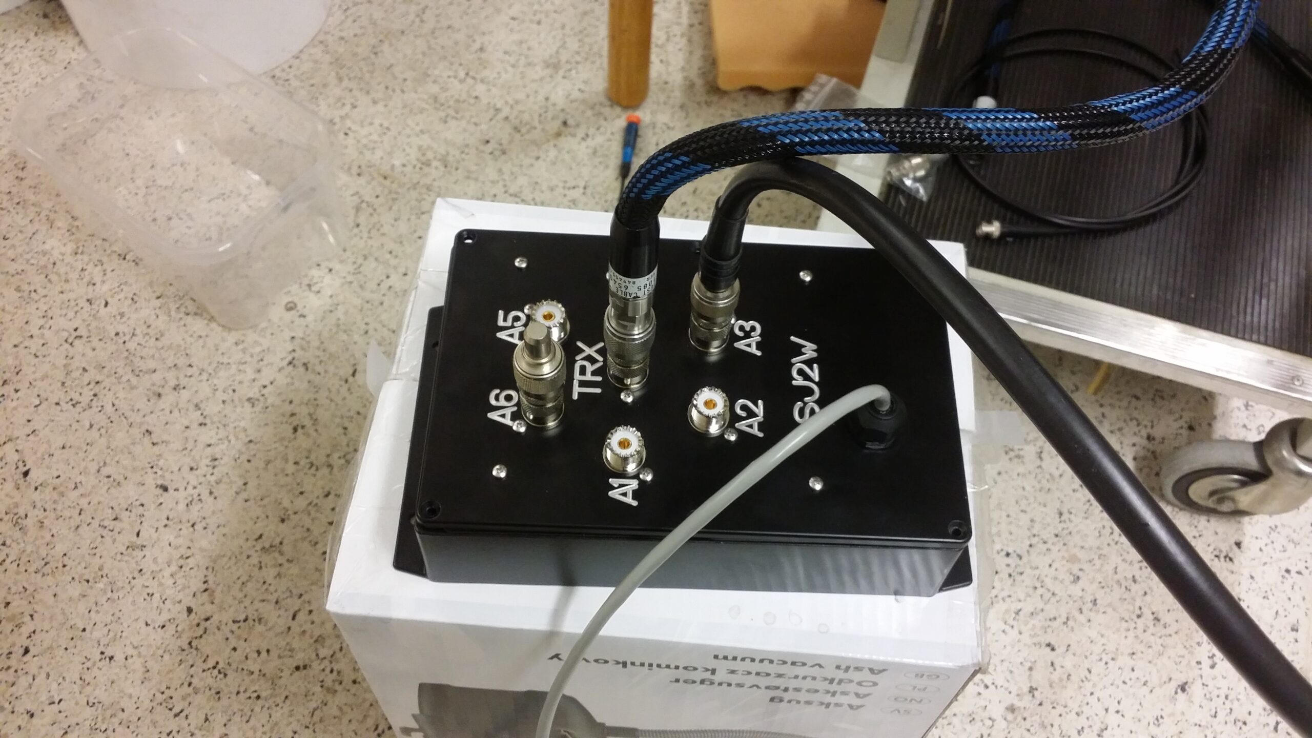
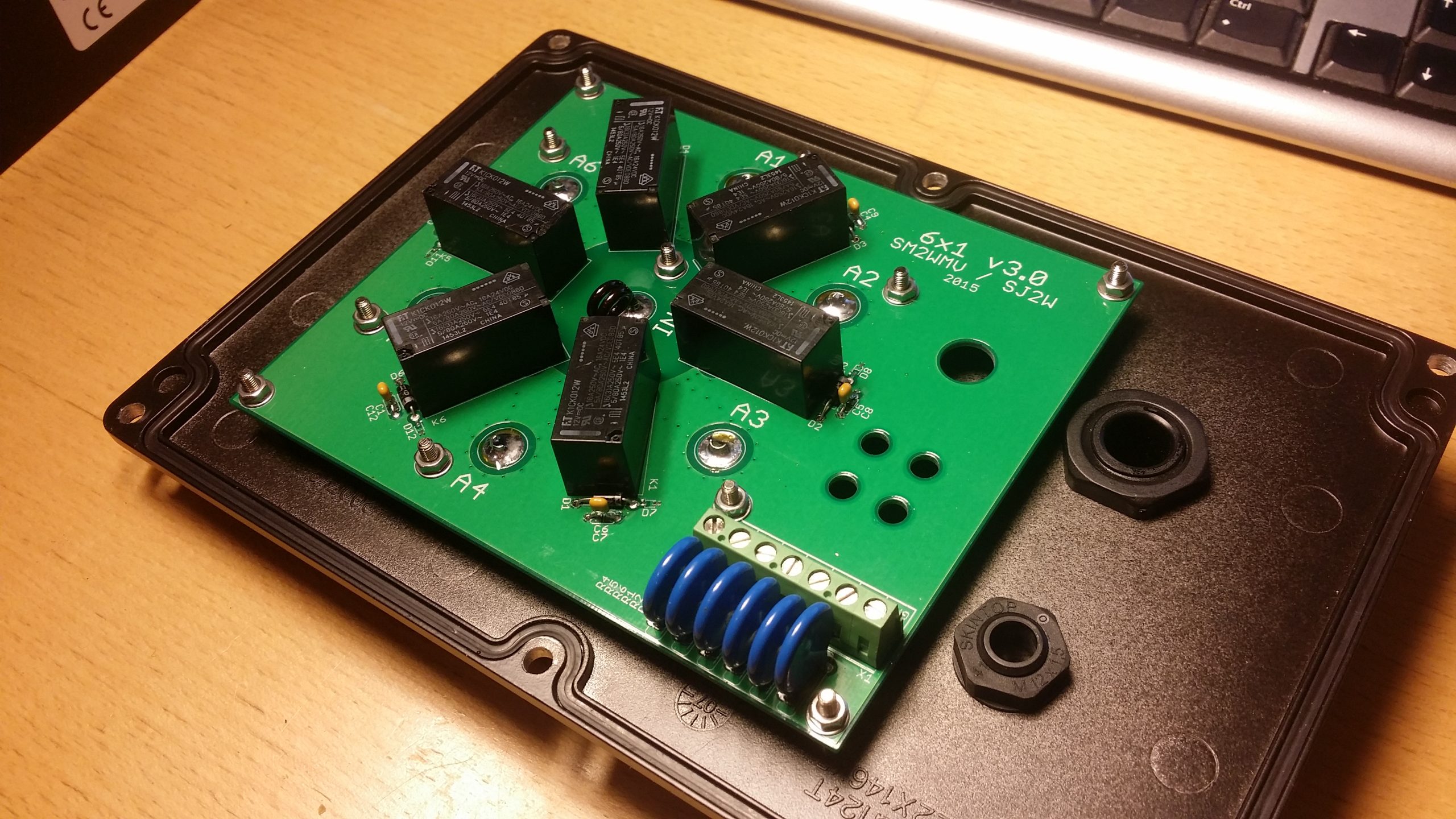
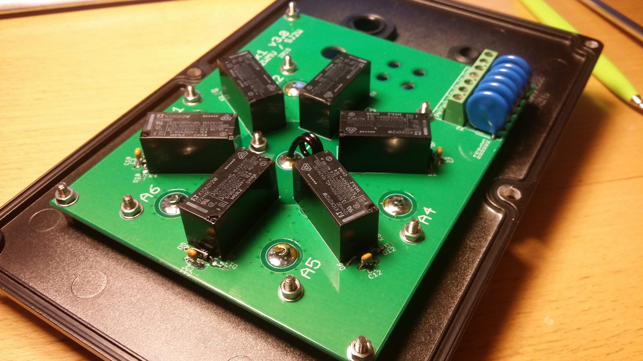
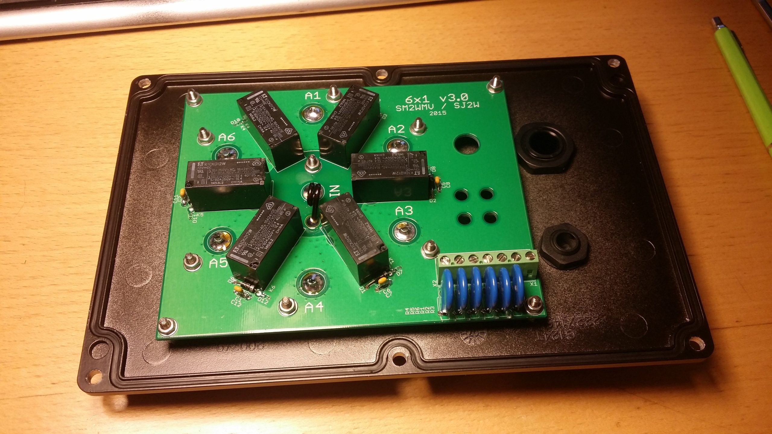
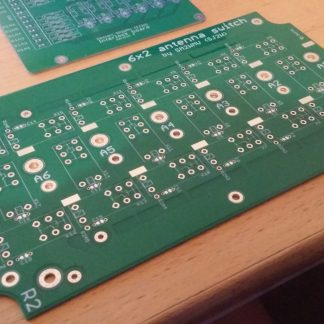
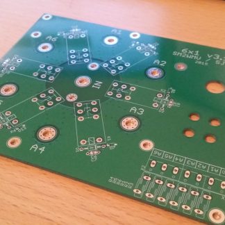
The 6×1 is an antenna switch which has got 6 antenna outputs which can be routed to one radio input. When an antenna output is not used it is grounded which is good against static discharges such as lightning strikes etc. The performance probably the best on the ham radio market and can handle up to 5kW with good VSWR.
The device uses positive switching, which means all the relays use common ground. So to enable an antenna you would add a voltage of +12V on the control line. 7 leads are needed to control the box, so a network cable is perfect to switch it.
Isolation 50 MHz, -55dB
Isolation 28 MHz, -60dB
Isolation 14 MHz, -70dB
VSWR < 1.04:1 on 1.8 – 50 MHz
Insertion loss < -0.04dB
Power rating (1.8-30 MHz, SWR <1.3:1) 5kW
Power rating (1.8-30 MHz, SWR <2:1) 2.5kW
Power rating (1.8-30 MHz, SWR <3:1) 1.5kW
Power rating 50 MHz 2.5kW
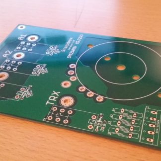
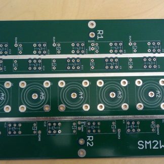
Top print of board (scale 1:1)
Remember to always disable scaling when printing the top print of the board to use as a drill template, so that you are sure you are having a 1:1 scale print.
To get optimal performance out of the switch with lower insertion loss, an inductance should be soldered on the board as can be seen on the pictures. A good starting point is 1.5 turn around a 4.5mm rod (use a 4.5mm drill bit). I would say with this you will get close enough to perfect performance but you can verify it if you have access to some kind of VNA. You will get very close to perfect performance also by just soldering a piece of wire instead of this inductance.
Reviews
There are no reviews yet.