


Description
The stacker is a device which is used to split power between up to three antennas. It can be used to switch antennas in a stack or for beaming multiple directions. A stacking system that is made this way is simply an approximation of a two way and three way stack. The UN-UN transformer has got a ratio of 2.25:1 and that way you will get about 56 ohm with two 50 ohm antennas connected and 37.6 ohm with three antennas connected. That gives you a reasonable SWR in both cases. You can also use it as a regular antenna switch for three antennas and of course it is switchable between these different modes. This model of the stacker has also got an A/B output which is basically a port of the 6×2 switch. This makes it possible to route the antennas out to either A or B and can with two 6×2 switches expand the system to be used on four radios to six bands with three antennas per band.
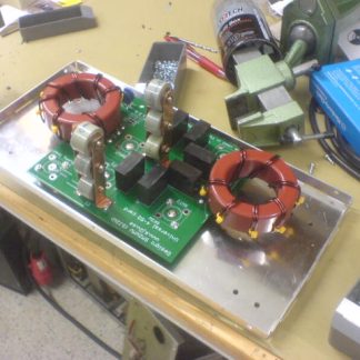
I recommend using a FT240-61 core to wind the UN-UN transformer. If you are using legal limit power levels then one core is enough but going over 2kW I would recommend using two cores. If you want to use the stacker on all HF frequencies I would recommend that you wind it five turns trifilar (three wires in parallel) around the core with copper emelded wire. If you wish to optimize it for 10m I would recommend using 4 turns and if using it on low (80,160m) frequencies I would recommend 6 turns. Make sure that the wires are in parallel so that they do not cross over each other anywhere and then remove the varnish and solder them straight down at the UN-UN position of the PCB.
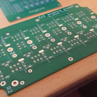
To avoid breaking up the ground plane of the PCB you must solder wires from the input control lines to each relay, but this is clearly marked out on the PCB. Solder shields around the relays K5,K6,K7 to increase isolation between port A and B. If you don’t need the option to route antennas to two outputs you can just solder jumpers underneath the PCB and skip mounting these relays.
As the other boards it is 140um copper and can handle > OM-3500 power levels without any problem.
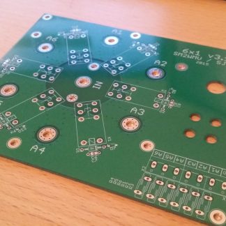
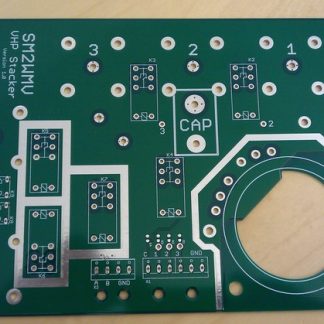
Top view of the board – If used as a drilling template, make sure to print it as 1:1 scale.
| Ant combination | 1 | 2 | 3 | C |
| A1 | 1 | 0 | 0 | 1 |
| A2 | 0 | 1 | 0 | 1 |
| A3 | 0 | 0 | 1 | 1 |
| A1+A2 | 0 | 0 | 1 | 0 |
| A1+A3 | 0 | 1 | 0 | 0 |
| A2+A3 | 1 | 0 | 0 | 0 |
| A1+A2+A3 | 0 | 0 | 0 | 0 |
On the pictures you can see an option to add a coil if needing to lower the insertion loss when using single antennas. However I haven’t seen this being needed so just put a jumper between these two pads.
Reviews
There are no reviews yet.